This is an old revision of the document!
Table of Contents
⚠️ PAGE UNDER CONSTRUCTION!⚠️⚠
Fan: Maico ECA 100 ipro
Initially I just wanted to have an occupied signal for a bathroom in a shared flat the fan is installed in. Thing is, I had no PICKit in 2022, so I eventually decided to cut power of MCU: I realized I was going all in.
I hope this write up helps somebody repairing their PCB, provides an easy start for modifying or is at least a pleasant nice2know.
I am aware that Maico offers interconnected fans and aftermarket PCB (e.g. ECA 150 ipro RCH) - it is just really expensive and is not what I was looking for.
What I wanted to achieve with a replacement MCU:
- have an occupied signal
- get rid of annoying, timer based only trigger
- light switch toggle to turn fan on/off
- turn on fan on high humidity
- easy way to configure: web-interface
- → I wanted to have WiFi as the shared flat has no smart home which it could be integrated into
- night mode (gets time from NTP)
- stopwatch pee time game for fun
Disclaimer
⚠️ The PCB is connected to mains 230VAC! Be aware of what you do. This is no kids game, it can be life threatening or worse if you are not careful.
I am not responsible for anything you do, this is not meant to be a tutorial to mimic. It is just a write up of the steps I have taken to achieve a goal I have striven for.
Link to original manual
reverse engineering
The fan consists of a 1-phase AC motor, a PCB controlling it and the shell/casing.
Unmodified ECA 100 ipro series has the following hardware on PCB:
MCU: PIC16F677 -I/SS
AC/DC: LNK304DN
Optocoupler: P185
Triac: ST T405Q 600
varistor: S10K275
input cap1: 400V 4.7
On some PCBs it's nearly impossible to read part numbers on the backside of PCB as the high voltage portion on the backside is painted in clear protective glue(?). For measurements I have just scratched it.
The backside of the PCB has unfortunately no silkscreen, that is why I have made up names for test points.
I have quickly ordered all parts in KiCad according to PCB layout - (Yes, I am well aware that schematics are normally not drawn like that. It is only my shared notes; if you want to pick up on them and create a board layout, go for it :)). It might contain errors, I actually haven't checked.
Tldr schematics; LNK304 provides 5V power with opto-coupler as feedback. Resistors scale down voltage for AC-wave signal, which is fed into PIC16 via transistors. PIC16 triggers Triac (according to AC-wave).
 schematics without MCU
Download KiCad (>=v6) schematics, complete with PIC16 pinout: Todo <insert schematics>
Interesting to see is that the Triac switches Neutral, not Live conductor: in my world that is considered bad practice.
for us imporant pins on PIC16
| Pin# | Name | description | additional info |
|---|---|---|---|
| 1 | VCC | 5V | cut pins 1,2,3,17 not only VCC! |
| 2 | FAN | output: trigger signal for Triac/Fan | goes over R13 to Triac |
| 3 | Light | input: light signal | |
| 17 | ACF | input: (AC frequency) AC wave signal for syncing | |
| 10 | Button left | time till turn on select | |
| 12 | Button right | overrun time select | |
| 5-8 | LEDs 1-4 | ||
| 20 | GND | Ground | ⚠ directly connected to N-line! |
for alternative (test) points, see newly created PCB scan :) \\

logic analyzer capture
The Triac is triggered by PIC16 synced to AC-wave signal (provided by opto-coupler). Triacs do not turn off automatically again if fired, unless voltage drops to 0V (or complicated circuit added). So what you see on logic analyze capture is just the triggering signal for Triac (D0), not its durance it is turned on. The durance is the point the Triac is triggered till signal of opto-coupler (D1) is low (and therefore AC-wave crossing 0V).
The fan has originally only two settings, configurable via jumpers: slow (78m³/h) and fast (92m³/h).

PCB scan
In 2025 I got hands on a broken, water damaged PCB on Kleinanzeigen, more than three years after the start of the project. I desoldered all parts and scanned the PCB for your convenience. I did not have any solvents but acetone nail polish at hand, which does not work that well with the sticky glue. What I did is heat the glue with hot-air rework station and wipe most of it off with a cloth - the mite rest was removed with acetone (nail polish).

I admit, I have not cleaned the board properly, as it was corroded and toast anyways.
The trace of L-line was burned up of this broken PCB, I have redrawn it in pink to show the original trace.
Thanks to the PCB scan, you can see the needed points easily where to solder the wires to.
Board repair
The broken board I got from Kleinanzeigen has (at least) burned Varistor (VDR1) and capacitor C1. Check for burned through PCB traces and replace those two parts.
Also try disconnecting the original sensor (if your version has one) - the humidity sensor I got bundled with is bad too.
original humidity sensor
Together with the broken PCBs, I got a humidity sensor (which I did not have at the time of the project). The sensor is glued into a plastic shell, the glue looks to be the same as on the backside of the PCB.
The plastic cover of the housing has a rubber cover, which is cut open if a sensor is installed. Tip to close it up again: put crepe tape over the hole and close up with hot glue from the other side.
#TODO: insert pinout + resistor values
communication protocol / find out sensor type?
Don't have a sensor (version) like me? Read on.
PIC16 Firmware dump
As I now own a PICKit (I have not at the time of doing this project), here is the firmware dump of a PCB with humidity sensor: <insert dump>.
I do not know if firmware differs for models w/o sensor, as the original PCB is still doing its duty in the shared flat. My guess: probably same firmware; the pin header is unpopulated.
Hardware modification
MCU replacement: cut traces of PIC16 (at least pins 1,2,3 and 17) or desolder completely.

The following modifications will be done:
ESP8266-12F for WiFi
↳ needs LNK306DN buck converter upgrade!
ASM1117-3V3 LDO module (5V to 3.3V)
Humidity+Temp sensor (HTU21D)
Why ESP8266? Because:
- it has WiFi and sufficient GPIOs
- peak power barely fits output limit of LNK306 (unlike ESP32 variants)
- it fits physically into the original housing as PCB-sandwich
- I had it lying around and it is cheap (~1.3€)
To squeeze in all that hardware, build a sandwich with hot glue as sauce between the layers:
* ASM1117-board fits on the front side below the buttons (I admit, it is necessary to grind off a bit at the edges). Requirement: Pin headers for original sensor needs to be unpopulated (desolder otherwise).
* Solder SMD resistors directly on the underside of ESP8266-12 (see picture closely), so no space is wasted.
* Add humidity sensor breakout board in the plastic cover of housing (HTU21D fits nicely after grinding a bit off)
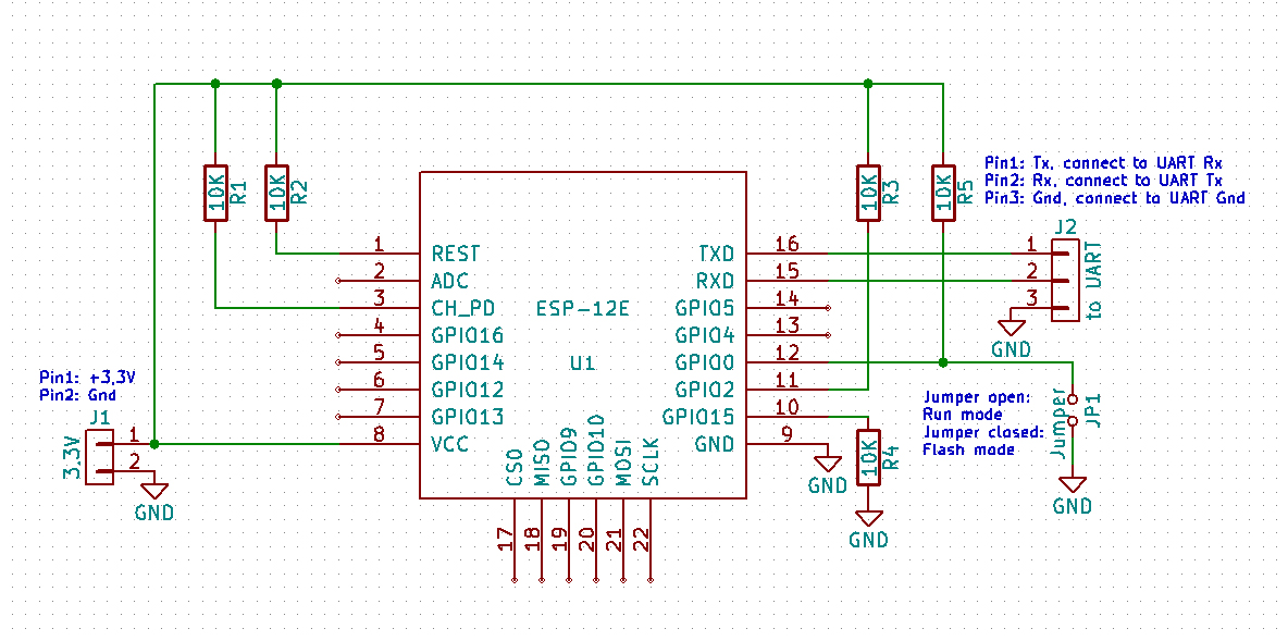
See schematics on letscontrolit.com/wiki for ESP-12 module to connect needed resistors
⚠️ ESP8266 draws way more power than PIC16: It is mandatory to upgrade LNK304DN to LNK306 for sufficient power! If you have no SMD-rework station, desolder pins one by one by bending each pin up - alternatively cut pins with a rotary tool carefully.


⚠ Remember: NEVER solder rigid cables onto SMD pads like TestPoints! The leverage is high, so is the danger to rip off the pad - use flex cords.
See PCB scan where to solder wires for FAN, ACF and Light-signal
You might want to cut traces of jumper pins and misuse the 4-pin header for flashing (VCC, GND, RX+TX).
Repurpose existing buttons by connecting them to ESP for GPIO0 flash-mode and reset pin.
The LEDs are unused, as there are not enough GPIOs (does not matter as there is a webpage for config)
To install the humidity sensor, I have cut a small hole of the size of the sensor IC into the rubber.
⚠️ Seal rubber of housing cover when installing humidity sensor with hot glue! No moisture allowed on the PCB, this is still mains AC!
Pinout ESP-12
| Pin# | name | description |
|---|---|---|
| 1 |
Firmware
As this project was intended to be for a shared flat which I actually do not live in, I made the mistake to start the project using Arduino. Why? Actually, I don't know anymore 🤡 I wanted it to be maintainable easily by another person. Oh, well, there is always a next project to avoid Arduino.
For initial flashing you need a UART-USB adapter (USB to TTL converter), e.g. CH340, CP2102 or similar.
⚠️ Do not power PCB by AC for flashing. Mains Voltage is dangerous for you and your computer! Always use VCC of USB-adapter.
Later on you can use OTA for flashing (unless/until you screw up)
OTA
Update ESP8266 Firmware either via ArduinoOTA or upload firmware image on html-page /ota-update.
See button config how to put ESP into ArduinoOTA mode.
Use esp8266littlefs-plugin to upload .html files to LittleFS - (tutorial e.g. on randomnerdtutorials.com).
Button config
Repurposed buttons: Right button resets the ESP. The left one puts ESP into Flash-mode if RESET pressed together with it. To go into OTA-mode for ArduinoOTA, RESET then wait ~2s and hold left button till connected to WiFi.
Interrupts
The ESP8266 has two hardware timers: Timer0 is already used for WiFi, making only Timer1 available for user-defined timer interrupts.
We need an interrupt to detect AC-wave signal and could use another timer-interrupt to generate a signal to trigger the triac for the motor, which makes two interrupts. The trick is that we do not need them concurrently as the triac is only triggered when AC-wave signal is high. So we can use Timer1 for both interrupts by switching it back and forth between AC-wave and motor signal generation.
WiFi + Webinterface
As ESP8266 has WiFi, let's use it for a nice web interface. For simplicity it runs on Arduino with ESPAsyncWebSrv-lib. To sync the values of the variables in firmware with html, I have chosen to use AJAX with JSON format.
If WiFi is unable to connect, ESP is put into access point (AP) mode. Connect and go to 192.168.4.1 to change SSID+password.
To change network settings (mDNS-name, IP) later on, go to /wificred (default AP page).
Go to /settings to change fan specific stuff.
As seen in the screenshot, I have used the word “kacken” a lot, which is informal German for “(to) poop”.
There are GET commands (REST) to control the fan too.
/kacken: puts fan into kack-mode
/aus: turns fan off. will be overridden on changed mode
/peestart: starts peeing game
/pissoff: stops stopwatch of game
pee game
What the heck is a pee game? Not another fetish, you already have all those cables and electronics?!
Relax, it's a time based game which was played in the shared flat:
Are you quicker (with washing hands thoroughly!) than a predefined time (~1min)? Turn light on, do your duty and turn light off again. If you are too slow, the fan spins shortly to acoustically signal that time has passed and you have lost! Check your time on the web frontpage - you can start+stop the stopwatch game there too.
#Todo: add scoreboard leadership with acronyms/name entries.
MQTT
#TODO: Still missing. HeartBeat for smoke detector.
As ESP8266 only provides WiFi as wireless communication, MQTT is added for a proper way to add the fan to smart homes.
Todo
- build external, wireless WC-occupied LED-sign
- play tones over fan noise - feasible?
- interconnect several fans
- If I had more GPIOs: add motion/presence detector; add night light; add poop smell sensor; add DC-motor interface for air-freshener spray
poop smell sensor
What actually causes poop odor? Main contributors:
- Hydrogen sulfide (H₂S) — rotten-egg smell
- Ammonia (NH₃)
- Volatile organic compounds (VOCs) — mercaptans, indoles, etc.
MOS VOC sensors are good for: “Something smells off”, not “It’s poop”, which is fine for this case. Therefore BME688 or SGP40 would be choices to investigate in.
Conclusion
The PCB is optimized for low cost, as you can see on the series resistors for light detection. I like the design, it is not over complicated.
The modification project was fun. The ESP8266 is doing its job for ~3 years now (time or writing) without any issues.
What would I do differently if it was my product? I would build it more modular with proper galvanic isolation from logic level to mains AC and switch Live instead of Neutral with Triac. An MCU with Zigbee would be better suitable for smart homes. Actually, I have build the circuit as schematics already. @Maico: Are you interested? ;)
Bonus: the fan itself
As written in section PCB scan, I have gotten a burned up fan with water damage on Kleinanzeigen.
So, how do disassemble it?
- pull off fan rotor to the front (it is tightly stuck onto the shaft, consider winding a string behind all rotor blades and pull on that)
- losen all obvious screws