Table of Contents
When 💩 hits AC-Fan: Maico ECA 100 ipro VZC
Update
@VIEGA: Ich habe am 04.05. meine Visitenkarte in der Niederlassung Chur gelassen, da ich die Mailadresse von Herrn Cajacob nicht richtig geraten habe. Ich hatte auf der IFH Intherm gesehen, dass eins Ihrer Produkte der RFC 1918 widerspricht. Ich würde mich über eine kurze E-Mail von der Entwicklungsführung als Kontaktaufnahme freuen.
#Info: Der gescannte QR-Code ist auf dieser Seite gelandet, da sie ein reverse engineering Projekt von mir zeigt - zumindest teilweise, der Softwareteil wurde absichtlich derzeit entfernt.
Ich suche derzeit nach einem Sponsor für Hardware wie Maico ER EC NFC oder auch Helios-NFC-Serie. Warum? Weil RE Spaß macht :) Was hat der Sponsor davon für ~500€ Hardware zu stellen? Hoffentlich ebenfalls Spaß daran und kostenloses reverse engineering für alle 
I am aware that this page does not make as much sense as before, having separated it from the fun part of replacing the MCU and the development of the software - 💩 happens. It will be made public again soon, as I am currently creating a smart custom PCB for ECA100, which will be made OSHW (open Hardware). Stay tuned :) Till then, enjoy the reverse engineering part.
OC
Initially, I just wanted to have an occupied signal for a bathroom in a shared flat the fan is installed in. Eventually, I decided to cut power of MCU: I realized I was going all in, a replacement MCU was needed.
I hope this write-up helps somebody repairing their PCB, provides an easy start for modifying or is at least a pleasant nice2read.
I am aware that Maico offers interconnected fans and aftermarket PCBs (e.g. ECA ipro RC(H)) - it is just not what I was looking for.
It was supposed to be “smart”, but what does “smart” mean in this case? To me, a well suited solution (for a non-smart-home shared flat).
Read <HERE> about what I have done with replacing the MCU #TODO: insert link here ← This part is gone for now.
Read on but don't let the 💩 hit the fan! (no pun intended) - take care.
Disclaimer
Think. I am not responsible of what you do. This is for educational purposes out of curiosity and my personal use only.
⚠️ The PCB is connected to mains 230VAC! ⚡︎⚡️ Be aware of what you do. This is no kid's game, it can be life-threatening or worse if you are not careful. Have an LED-light ready when you cut power to bathroom in the fuse box.
I am not responsible for anything you do, this is not meant to be a tutorial to mimic. It is just a write-up of the steps I have taken to achieve a goal I have striven for.
Link to original manual
If you feel not comfortable with a repair, get original ECA100 ipro VZC circuit board for 73€ with cover and 81€ with pin header for sensor. 🧂
I am not affiliated, nor does this project violate any copyright (AFAIK, if you feel different, contact me). No, I do not sell any hardware. Seriously, just buy a genuine Maico replacement PCB if yours should be broken, avoid danger. ⚡︎⚡️💥🔥
As mentioned on the start page: Except where otherwise noted, all content on this domain is licensed under a Creative Commons Attribution-NonCommercial-ShareAlike 4.0 International License (CC BY-NC-SA 4.0).
The missing information
Before the fun part, let's start with the information which are missing in the manual.
- The braid wires of the fan should not be twisted! (do not even think about tinning them, you will never get them out of the socket).
- Get the correct screw driver for the fan socket J2 to push the contacts down.
- The fan connector J2 has double socket holes, the K-version has the shutter connected to it too.
- The H-version has the following fixed control of humidity values: https://youtu.be/7UQG8KkPfLs?si=7md-VcyXBfDmjr59&t=92
- Do not be fooled by that ad-video: changing programms is not easy. It requires taking of the lid to push the buttons to change timings. To change speed programms, it is necessary to even take off the cover of the housing to change jumper placements, which theoretically requires to cut power (and then you cannot see anything b/c the ceiling light is probably on the same fuse)…
- The fan PCB is a NON-ISOLATED design. So DO NOT mix up VDE-colors or the whole ground-plane might be under 240VAC!
Reverse Engineering
The fan consists of a single phase AC induction motor, a PCB controlling it and the shell/casing.
Unmodified ECA 100 ipro VZC series has the following hardware on PCB:
MCU: PIC16F677 -I/SS
AC/DC: LNK304DN
Optocoupler: P185
Triac: ST T405Q 600
varistor: S10K275
input cap1: 400V 4.7
On some PCBs it's nearly impossible to read part numbers on the backside of PCB as the high voltage portion on the backside is painted in clear protective glue. For measurements, I have just scratched it. You can melt the glue carefully to close up the scratches again - do not burn components or anything, rather try out Plastik 70 (no ad, not tried out yet).
The backside of the PCB has no silkscreen - unfortunately, that is why I have made up some names for test points, e.g. ACF (=AC Frequency input)
I have quickly sorted all parts in KiCad according to PCB layout - with some imagination. Yes, I am well aware that schematics are normally not drawn like that. It is only my shared notes; if you want to pick up on them, separate parts and create a board layout, go for it :). It might contain errors, I actually haven't checked.
 badly drawn schematics without MCU
TL;DR schematics: LNK304 provides 5V power with optocoupler as feedback. Resistors scale down voltage for AC-wave signal, which is fed into PIC16 via transistors. PIC16 triggers Triac (according to AC-wave).
Download KiCad (>=v6) schematics, complete with PIC16 pinout: Todo <insert schematics>
I have started to recreate the PCB itself, but have abandoned it.

Why have I abandoned to recreate the PCB? Because I think I can improve this design. Very clever how non-isolated zero-crossing detection of two signals is done with only three transistors.
“Interesting” is that the Triac switches Neutral, not Live conductor: in my world that is considered bad practice. There also is no snubber at the TRIAC present, (which is not snubberless).. Is there something I do not see here?
Pinout of PIC16
| Pin# | Name | description | additional info |
|---|---|---|---|
| 1 | VCC | 5V | cut pins 1,2,3,17 not only VCC! |
| 2 | FAN | output: trigger signal for Triac/Fan | goes over R13 to Triac |
| 3 | Light | input: light signal | |
| 17 | ACF | input: (AC frequency) AC wave signal for syncing | |
| 10 | Button left | time till turn on select | |
| 12 | Button right | overrun time select | |
| 5-8 | LEDs 1-4 | ||
| Connection to pin-header | header for Maico humidity/motion sensor | #TODO insert pinout | |
| 20 | GND | Ground | ⚠ directly connected to N-line |
 first testing steps with PCB wire
for better (test) pads, rather see chapter modification or even better the newly created PCB scan :)
logic analyzer capture
The Triac is triggered by PIC16 synced to AC-wave signal (provided by opto-coupler). Triacs do not turn off automatically again if fired, unless voltage drops to 0V (or complicated circuit added). So what you see on logic analyze capture is just the triggering signal for Triac (D0), not the duration it is turned on. The durance is the point the Triac is triggered until signal of opto-coupler (D1) is low (and therefore AC-wave crosses 0V).
The fan has originally only two speeds, configurable via jumpers: slow (78m³/h) and fast (92m³/h).

Interesting to see is that duration of positive and negative part of AC wave is different (11.75ms vs 8.25ms). Timings differ in speed modes: In the first, the firing of Triac in negative AC part is off by 1.55ms, I believe to compensate the differing duration. In the second mode the Triac is always fired roughly in the middle of the intervals, so there seems to be no compensation. Makes me wonder if this is intentional or just a mistake.
PCB scan
More than three years after the start of the project, I got hands on a broken PCB (due to water damage) on Kleinanzeigen in 2025. I desoldered all parts and scanned the PCB for your convenience. I did not have any solvents but acetone nail polish at hand, which does not work that well with the glue getting sticky the AC part of the PCB backside is painted with. Is the glue what they call “Plastik 70”? What I did is heat the glue with hot-air rework station and wipe most of it off with a cloth - the mite rest was removed with acetone (nail polish).

#TODO: add size measurements of PCB in photo scan and names for pads+components on backside of PCB
I admit, I have not cleaned the board properly, as it was corroded and toast anyways.
The trace of L-line was burned up of this broken PCB, I have redrawn it in pink to show the original trace.
According to the datasheet, the PCB is 18 x 20 x 125 (Width x Height x Depth in mm) in size. In my POV, the depth would rather be the height. I have measured the PCB myself and it is 18mm x 127mm.
Thanks to the PCB scan, you can see the needed points easily where to solder the wires to for modifying the hardware.
Board repair
The broken board I got from Kleinanzeigen has (at least) burned Varistor (VDR1) and capacitor C1. Check for burned through PCB traces and replace those two parts.
To desolder C1 with iron, wind tinned braided wire around so it is soldered to both pads for heat transfer. This way it is easy to remove SMD parts without ripping off pads. The flux may be with you.
Also try disconnecting the original sensor (if your version has one) - the humidity sensor I got bundled with is bad too.
original humidity sensor
Together with the broken PCBs, I got a humidity sensor (which I did not have at the time of the project). The sensor is glued into a plastic shell, the transparent glue looks to be similar to the one on backside of the PCB.
The plastic cover of the PCB housing has a rubber cover, which is cut open if a sensor is installed. Tip to close it up again: put crepe tape over the hole and close up with hot glue from the other side.
#TODO insert photos
#TODO: #TBD insert pinout
communication protocol / find out sensor type? → not really worth the hassle.
Don't have a sensor (version) like I did not? Read on. I have replaced it with SparkFun HTU21D sensor.
No PIC16 Firmware dump
#TBD
As I now own a PICKit3 (I have not at the time of doing this project)… I still have not connected it, because I then only will realize that it probably has readout protection in place.
The principle of PIC16 firmware has already been reverse engineered, no need for a hex dump.
I do not know if firmware differs for models w/o sensor. My guess: probably same firmware; the pin header is unpopulated.
Hardware modification
⚠ Always make sure casing of electronics is sealed against moisture properly again! The PCB-scan shows what happens if not. 240VAC ⚡ water 💧 = 🌋 magic smoke 💨 or 🧯🔥. Keep in mind that mains part of PCB is painted with some glue on the backside for a reason.
MCU replacement: cut traces of PIC16 (at least pins 1,2,3 and 17) or desolder completely.
See the photo for a suggestion where to cut traces carefully. This is only reversible if you fix the traces. Scars will be left, do not burn any SMD-caps.

The following hardware modifications will be done:
ESP8266-12F for Wi-Fi
↳ upgrade buck converter to LNK306DN!
ASM1117-3V3 LDO module (5V to 3.3V)
Humidity+Temp sensor (HTU21D)
Why ESP8266? Because:
- it has Wi-Fi and sufficient GPIOs
- peak power fits output limit of LNK306
- it fits physically into the original housing as PCB-sandwich
- it is what I had lying around in 2022 and was cheap (~1.3€)
- there was no ESP32 C-series in '22
To squeeze in all that hardware, build a sandwich with hot glue as sauce between the layers: 🥪
- Wait! Have you upgraded to LNK306DN already? If not, do so now, this is mandatory! Read below how to.
- ASM1117-board fits on the front side below the buttons (I admit, it is necessary to grind off a bit at the edges to ensure it is not longer than PCB). Requirement: Pin header for original sensor needs to be unpopulated (desolder otherwise) and lower plastic pin-clip for PCB needs to be trimmed/cut down.
- Solder SMD resistors directly on the underside of ESP8266-12 (see picture closely), so no space is wasted.
- Add humidity sensor breakout board in the plastic cover of housing (HTU21D fits nicely after slicing in a hole in the rubber of the cover). Why HTU21D? Because I had it lying around. There are other sensors which could fit too, e.g. SHT30/31, AHT20/30, Si7021, BME280, etc. Check measurements if the breakout board would fit.
#Note: modern way would be to use a RISCV-MCU board with ESP-IDF. ESP32-C3 / C6 super mini should fit the space too and can also be powered by LNK306. There was no C-series when I have done this project.
⚠️ ESP draws way more power than PIC16: Upgrade buck converter to LNK306DN as drop-in replacement for sufficient power. There are pages with current measurements, e.g. for ESP8266 here. LNK304 is not suitable for the peak currents of ESP.
If you have no SMD-rework station, desolder pins one by one by bending each pin up - alternatively cut pins with a rotary tool before carefully. Drop and solder in LNK306 as replacement IC. Don't forget to wash off flux with isopropyl alcohol (and consider restoring protective, non-conducting glue coat with Plastik 70?). I have not used my SMD-rework station either here, which was a good idea b/c the moisture sealing glue over the PCB and components is a sticky mess when heated up over a large area.
⚠️ You do not find EMC tests here, (even though I have at least some EMI test equipment). The electrical measurements are fine, LNK306 works for me 24/7 for ~3 years now.
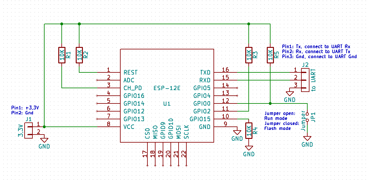
See schematics on letscontrolit.com/wiki for ESP-12 module to connect needed resistors. If you solder one side of SMD resistors directly on the pad of ESP12 underside and the needed wires on the other side of the resistors, no space is wasted (1st photo, see magnified where the red arrows are). Consider fixing resistors and wire joint with glue, I have chosen UV-glue. Unfortunately, I have not taken a photo of that.
See chapter PCB scan to see where to solder the wires.
Now make the sandwich with hot glue as sauce between the layers:


🥪 prototype setup
So the sandwich consists of the main-PCB (space below the buttons) as the base, with (trimmed) ASM1117 breakout board, topped off with ESP8266. The cables routed between the layers is the spaghetti speciale. As the cherry on top, the humidity sensor breakout module is stuck inside the plastic housing with a hole cut into the rubber cover for the sensor-IC, sealed by hot-glue. Trim/cut down lower plastic pin-clip of housing for PCB.
Tip: ASM1117 LDO module only needs GND once (it is a rail) so you can skip the cable for GND “out”.
⚠ Remember: NEVER solder rigid cables onto SMD pads like TestPoints! The leverage is high, so is the danger to rip off the pad. PCB wires might be too labile - use proper flex cords.
⚠ take some sandpaper and make PCB a smidge narrower with round edges so no wires are accidentally squeezed
Keep everything isolated AFAP and/or add prophylactic isolation
See PCB scan where to solder wires for FAN, ACF and Light-signal.
You might want to cut traces of jumper pins and misuse the 4-pin header for UART (VCC, RX,TX, GND) to easily flash - mark it »no jumpers!«
Repurpose existing buttons by connecting them to ESP for GPIO0 flash-mode and reset pin.
I have not connected the LEDs, as there is a webpage for configuration, no reason to be all 90's. You might use GPIO# 1,2,15, which are still unused.
To install the humidity sensor, I have cut a small hole of the size of the sensor IC into the rubber.
⚠️ Seal rubber of housing cover when installing humidity sensor with hot glue! No moisture allowed on the PCB, this is still mains AC! ⚡
As the new humidity sensor is not as raised as the original one, you have to cut away some plastics of the outer fan housing so the sensor is “free to breathe”.
#TODO: make and insert photo of humidity sensor rubber
Pinout ESP-12
| GPIO/Pin# | name | description | Note |
|---|---|---|---|
| 13 | ACF | ACF_PIN is signal of AC-wave frequency as binary logic | |
| 12 | LIGHT_PIN | Light switch detection with AC-wave logic signal | |
| 14 | FANOUT_PIN | switches triac on for fan | Triacs can actively only be turned on, not off. It turns off on crossing AC |
| 0 | button left | Flash-mode (+OTA) | has multi function |
| RST | button right | ESP-RESET → reboot | |
| 3 | RX | Do not connect any pins for UART if AC connected! power via USB only | |
| 1 | TX | free* | *HIGH at boot debug output at boot, boot fails if pulled LOW |
| 2 | free* | *HIGH at boot connected to on-board LED, boot fails if pulled LOW | |
| 15 | free* | *SPI (CS) Boot fails if pulled HIGH | |
| 4 | SDA | Data for humidity sensor | |
| 5 | SCL | clock for humidity sensor | |
| 16 | RST_WAKE | RTC timer to wake ESP | → Requires GPIO16 (D0) connected to RST |
| GND | Ground | ⚠ directly connected to N-line | |
| VSS | 3.3V from ASM1117 | LNK306→ASM1117→3.3V for ESP |
Of course you can use free GPIOs for the LEDs on PCB, but there are better ideas and good use cases.
Note: wake from deep sleep is only possible if GPIO16 timer is connected to RST. Otherwise Reset button has to be pressed (which better is wired to one of the buttons on the Maico PCB) or turn AC-power off+on.
Firmware
THE COMPLETE MODIFICATION SECTION HAS BEEN MOVED: #TODO <insert link HERE>
Actually, you have to wait for that. It will be made public again soon(ish).
Further ideas and USPs
This part is gone for now too.
Downloads
Let me download everything!
Well, this part is gone for now too. Stay tuned! :)
Peroration
The PCB is optimized for low cost. What I absolutely dislike is that TRIAC switches Neutral instead of Live conductor - and there is no snubber present?! (Question: Is this (not) built-in obsolescence?)
The modification project was fun, I got an understanding how this AC fan is driven. LNK was upgraded, only the optocoupler was killed by me by accident in the beginning and had to be replaced - no other harm done (besides the knife attack on PIC16 traces of course..) :D
PIC16 was upgraded with ESP8266, LNK306 and ASM1117-LDO module, sandwiched with HTU21. It is doing its job fine for ~3 years now (time of writing) without any issues (actually 24/7 w/o night power saving). ✅ Long term test passed.
What would I do differently if it was my product? I would solve the above mentioned problems and build it more modular with better galvanic isolation from logic level to mains AC. At least I'd switch Live instead of Neutral with Triac, add a snubber and get rid of the series resistors burning up all that energy.
@reader: I hope it was a write-up to enjoy :) Feedback and corrections welcome! Consider to donate some real cookies 🍪 as this page uses none.
Also help to solve the Riddle of ECA150 VZC (RC)
#note to myself: trying to be hip with emojis all over does not suite me.
Bonus: the motor itself
Obviously I could not take apart the fan in the shared flat. But as written in section PCB scan, I have gotten a burned up, rusty fan with water damage on Kleinanzeigen.
So, how to disassemble it?
- pull off fan rotor to the front (it is tightly stuck onto the shaft, consider winding a string behind all rotor blades and pull on that)
- pop off rubber sealed lid carefully on the back side (not glued, only stuck 👍 still handle carefully)
- losen all obvious screws on front and backside of fan
- take apart with brains - unlike me (motor toast⇒I ripped the case apart and lost a photo due to it.)


It has proper industry bearings. Some photos (-1) for you to enjoy.
Bonus 2: the Riddle of ECA150
I do not own ECA150, I have just stumbled across a nice photo of RC version on Kleinanzeigen (hope I don't violate any copyright? mail me). I have gotten curious about the ICs used on that PCB and am sharing guesses.


The etched “silkscreen” on the PCB says SIM300-0 / TCM300-0 module. According to the logo, a TCM300 868 MHz module by EnOcean is used. Link to pdf datasheet (2MB).
There are two big yellow caps and no L1-line input. The yellow caps have “1.3uF 250VAC SH-B” in red written on it. Combined with the fact that the motor connector J2 has 3 pins, we can conclude that the motor probably is a PSC-motor (Permanent Split Capacitor) and therefore only has one fixed speed.
The outputs are: 2x wire socket (J3 marked 1 | K) + 3x wire socket (J2 marked 1 | M | C). “1” is probably L-mains and “C” = Common / Neutral. Which leaves “M” as the auxiliary winding / Middle. J2 is probably used for an electrical shutter. Really disappointing that there is no mention of J2 and J3 wiring or any fan connection (or am I blind?).
What is the label of the IC “U1” cycled in red? I bet it is LNK30x?!
Pictures are hard to come by (probably best on Kleinanzeigen/ebay/online market) - I have not checked for long. Question remains: What is on the underside of the PCB?
A link to official Maico pdf datasheet (17.3MB, multi lang) here.
🎁 How does the back side look like and what can be read on the ICs? I give away a small, useful surprise grift to chose from for electronic tinkering: Just submit some good info or (broken) PCB
Send mail to: contribute@super-se.de - no spam please.
ECA150 ipro is a bigger fan (the number represents the duct diameter), here 150mm. Throughput is 200-250m³/h. There are now four modes (Comfort, Night, Save(?→Spar), Power) - why do I not have such cool names? *note to myself to rename “kacken” to power*
Apparently there is ECA100 ipro RC too. I do not know how it looks like.
For ECA150 see RC spare replacement PCB (for 318€?!) #Känguru side note: But 318€?! That's 636 DMark! That's 1272 Ostmark. That's at least 6360 Ostmark auf'm Schwarzmarkt! … Jaa, I know what you are now thinking … 6360€ today would be 127200 Ostmark auf'm Schwarzmarkt …
There is a cheaper version without wireless master/slave interconnect https://www.maico-ventilatoren.com/produkte/p/platinen-g59683/pl-eca-150-ipro-vzc-h-b-p132185 (for only 90€ on Maico HP).
What MCU does it use? PIC16 again? Then RC version probably shares the same MCU for motor control on the backside of PCB with added wireless module? I have no idea (yet?).
Maybe we should build things on our own again? Maico fun chapter #2?
There are at least two even more simplistic versions in 150-series. I have not investigated how they might work or what their features are.
Thank you @Maico for having provided a permission to cross-load the following pictures from their official website:


[RC | VZC | VZ | ipro K only]
name scheming and 2 cents
I wonder about the acronym lettered names. The are more simple, single sided PCBs (VZ version for mere 40€..). VZ has a single potentiometer to configure some value/parameter and 3x wire socket only. Question: The missing 'C' in VZ probably stands for “Control”, missing logic. And 'V' and 'Z'? Verzögerungs-Zeitschalter? - I am having a hard time guessing here, is this somewhere public or obvious? And “ECA”? “Einbau Compact Axial”?
I get “H” for humidity, “B” for Bewegung/motion, but why “F” when it is called “Lichtsteuerung” / controlled by light sensor? Double confusing as “H” is “Feuchte-Vollautomatik” and not humidity on the german Maico HP.
So what does ipro K stand for? eleKtrischem Innenverschluss? There is a version with only “K” letter, (no further suffix). It has 2x+3x wire sockets with only a huge cap and a resistor(?) (style coil?) on the front. I admit, would be fun to see how the lasts cents are shaped off of this product.
@Maico: Why does the name scheming sound like some of my variable names? ¯\_(ツ)_/¯ (this is no rant, just my unfiltered string of thoughts).
I have just googled economic news to Maico and have seen that the new generation has taken over with Mr. Müller & Mr. Beck in 2025 and that an NFC-App enabled version has been released? All the best! :)
*note to myself*: look into NFC-App / PCB
A kindly meant observation: If I look at the Maico HP, I feel not that I have a good guide to chose what I could use as a customer. If it was my product page, I would have a category product selector guide filtered by my special use cases via keyword filter. Then have some nice dynamic comparison overview of relevant products. I also had hard times finding spare part pages without a web search engine. It feels like a riddle to find out what is smart to chose - just my 2 cents. :)
Gathered info from pictures
On RC there is no optocoupler on the front side of PCB (is there one one the back side?). It is missing L1-light switch AC-input. How come cheaper versions have L1 light switch input, whereas RC does only have L+N? Is it motion sensor only? WT.. #note: check manual
There are three diodes around switching regulator(?IC label?), 680 µH inductor, the 4.7 400V cap, some minor parts and 4*100Ω next to the two fat caps (I wonder about).
One button, one LED, a pin-header for available sensors. TCM300 with wire antenna on RC version.
There are two large yellow 1.3µF 250VAC caps on the input(? or are they used with motor? Are that the new X-Class caps for EMI?)
The VZC (non-RC) version seems to be more similar to ECA100 ( - apparently there also is a RC(H) version for ECA100). Visually there seems to be an optocoupler and L1-light switch AC-input. It has two buttons, four LEDs and two jumpers.
It shares the two large yellow caps with RC-version though.
Side quest
How do other fan/ventilator manufacturers do it? How do the PCBs of ebm-papst look like? Like a Bosch.?
Oh, and I have just learned that there is some NFC-app enabled product line by Maico?!
Added 01/2026:
Helios
As time of writing, I am temporarily living in flat which has two fans from Helios, model M1/100 F and N/C version.
The fan in the shower room only runs slow in high humidity mode, the other in the WC never runs. The sticker on the cover has the wiring diagram printed on it. Configuration is done via DIP switches on PCB after having screwed off the plastic cover (DIP table inside cover). Connecting cable to terminal 1 or 2 changes behavior of fan too.
On opening, I have found out that the Varistor is totally blown, so no wonder it was not working at all.
I will try not to reverse engineer the whole thing too.


link to manual pdf (4.26MB); redirect to helios
As I try to resist to create schematics, here just a few thoughts what components are seen on the PCB:
There is not that much on the PCB. One L+N input and another double terminal. A relay turns on the fan via a transistor. There are two diodes (one in input), a coil and a varistor as protection on input. Voltage for PIC16 seems to be broken down by resistors only, there are two zener-diodes hidden too, below 10uF and 220uF caps.
The motor is a single phase AC induction motor. As seen in the screenshot below, the setting of the jumpers can have a series capacitor added, which limits the speed of the motor.
 Schematics of how jumpers work on page 15 in manual
I have connected a PICKit3 to see if MCU is still alive. The PIC16F616 has readout protection in place. The pins for connecting PICkit are right on the opposite PCB side of MCU.
VCC - MCLR - GND - ICSPDATA - ICSPCLK
There is another 4-pin header near one edge of PCB with pinout: (read from middle to edge)
Pin2 - VCC - GND - Pin3
It is used in “F” model for a humidity sensor breakout board with bus-wire soldered onto these pads. The main PCB seems to be the same as “N/C” model.
As the PIC answers, the defective varistor was removed for testing: Runs in manual mode but not when light switch is connected to other terminal for time interval mode. White 2pin-component (coil?) gets warm. Have measured zener-diodes, one of it seems dead. Two of the four input 4703 SMD resistors are worn out. As I have limited tools and components in this flat, my landlord got a new fan. The PCB I let RIP (for now), the motor is put aside as spare part.
This page has been visited 28x till now.
Summary
- ECA100 uses a single phase AC induction motor, ipro VZC uses TRIAC for speed control by chopping AC wave
- ECA150 probably uses PSC AC-motor (Permanent Split Capacitor) with fixed speed
- Helios M1/100 uses a single phase AC induction motor with series capacitor for fixed speed setting
- Maico EC-series uses BLDC motor with optional NFC in the cover lid
Moved content
The real fun part has been moved (as it will be published in a separate page)